How to Configure a Cisco Switch with a Windows DHCP Server Across Multiple VLANs
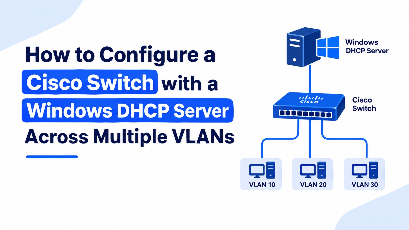
Small IT teams often need to split one physical network into separate departments without buying a server for each one. A single Cisco router, one Layer 2 switch, and one Windows DHCP server can handle that job together. This guide walks through a real lab build: two VLANs, a router-on-a-stick, and one centralized Windows DHCP server that hands out addresses to both networks through relay.
Table of Contents
- Lab Topology Overview
- IP Addressing Plan
- Why Router-on-a-Stick?
- Step 1 — Create the VLANs
- Step 2 — Assign Access Ports
- Step 3 — Trunk the Uplink to the Router
- Step 4 — Configure Router Sub-Interfaces
- Step 5 — Enable DHCP Relay (ip helper-address)
- Step 6 — Set Up the Windows DHCP Server
- Step 7 — Verify Everything Works
- Router-on-a-Stick vs. Layer 3 Switch
- Common Mistakes to Avoid
- A Note on DHCP Snooping and Security
- Conclusion
- FAQ
Lab Topology Overview
This build uses four devices connected through one Layer 2 switch:
- A Cisco 1841 router with one physical interface (Fa0/0), split into two logical sub-interfaces.
- A Cisco Layer 2 switch with VLAN 10 and VLAN 20 defined.
- PC8 on VLAN 10 and PC9 on VLAN 20, each plugged into an access port.
- A Windows Server running the DHCP role, connected to an access port on VLAN 10.
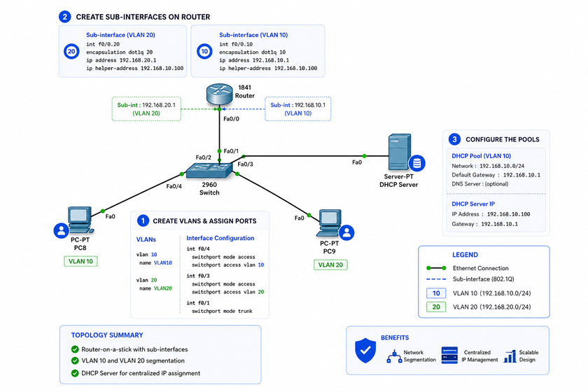
The router only has one cable running to the switch, so both VLANs travel over the same trunk. The router then separates the traffic using 802.1Q tags on two sub-interfaces.
IP Addressing Plan
Keep the addressing simple so troubleshooting stays easy later.
| Segment | VLAN | Gateway | Network | DHCP Range Suggestion |
|---|---|---|---|---|
| PC8 + DHCP Server | VLAN 10 | 192.168.10.1 | 192.168.10.0/24 | 192.168.10.2 – 192.168.10.99 |
| PC9 | VLAN 20 | 192.168.20.1 | 192.168.20.0/24 | 192.168.20.2 – 192.168.20.99 |
The DHCP server itself sits at 192.168.10.100 with a static IP and a gateway of 192.168.10.1. It stays out of both scopes’ lease ranges, since a server should never hand out its own address by accident.
Why Router-on-a-Stick?
A single router port can’t belong to two VLANs at once. Router-on-a-stick solves this by carrying tagged traffic for every VLAN over one trunk link, then letting the router’s sub-interfaces act as the gateway for each VLAN. Small labs and small offices like this setup because it needs only one router port and no Layer 3 switch. Larger networks usually move to a Layer 3 switch with SVIs instead, and the comparison table further down explains why.
Step 1 — Create the VLANs on the Switch
Log into the switch and build both VLANs before touching any ports.
Switch> enable
Switch# configure terminal
Switch(config)# vlan 10
Switch(config-vlan)# name Staff
Switch(config-vlan)# exit
Switch(config)# vlan 20
Switch(config-vlan)# name Guests
Switch(config-vlan)# exit
Naming each VLAN saves time later, especially when a network grows past four or five segments.
Step 2 — Assign Access Ports
PC8 and the DHCP server both belong to VLAN 10. PC9 belongs to VLAN 20. Set each port to access mode and lock it to its VLAN.
! Port connected to PC8
Switch(config)# interface fastEthernet 0/4
Switch(config-if)# switchport mode access
Switch(config-if)# switchport access vlan 10
Switch(config-if)# exit

! Port connected to PC9
Switch(config)# interface fastEthernet 0/2
Switch(config-if)# switchport mode access
Switch(config-if)# switchport access vlan 20
Switch(config-if)# exit

! Port connected to the Windows DHCP server
Switch(config)# interface fastEthernet 0/3
Switch(config-if)# switchport mode access
Switch(config-if)# switchport access vlan 10
Switch(config-if)# exit
Setting switchport mode access explicitly stops a port from negotiating trunk mode by accident, which is a common source of stray VLAN traffic.
Step 3 — Trunk the Uplink to the Router
The port facing the router must carry both VLANs, so it needs trunk mode instead of access mode.
Switch(config)# interface fastEthernet 0/1
Switch(config-if)# switchport mode trunk
Switch(config-if)# switchport trunk allowed vlan 10,20
Switch(config-if)# exit
Limiting the trunk to VLANs 10 and 20 with the allowed vlan command keeps unrelated VLANs off this link and reduces broadcast noise.
Step 4 — Configure Router Sub-Interfaces
On the router side, Fa0/0 stays down as a raw interface and hands the real work to two sub-interfaces, one per VLAN.
Router> enable
Router# configure terminal
Router(config)# interface fastEthernet 0/0
Router(config-if)# no shutdown
Router(config-if)# exit

! Sub-interface for VLAN 10
Router(config)# interface fastEthernet 0/0.10
Router(config-subif)# encapsulation dot1Q 10
Router(config-subif)# ip address 192.168.10.1 255.255.255.0
Router(config-subif)# exit

! Sub-interface for VLAN 20
Router(config)# interface fastEthernet 0/0.20
Router(config-subif)# encapsulation dot1Q 20
Router(config-subif)# ip address 192.168.20.1 255.255.255.0
Router(config-subif)# exit
Each encapsulation dot1Q command tells the sub-interface which VLAN tag to strip and accept, so it only sees traffic from that VLAN.
Step 5 — Enable DHCP Relay with ip helper-address
DHCP requests travel as broadcasts, and routers normally drop broadcast traffic instead of forwarding it. The ip helper-address command changes that behavior on a per-interface basis, converting the broadcast into a unicast packet aimed at the DHCP server.
Router(config)# interface fastEthernet 0/0.10
Router(config-subif)# ip helper-address 192.168.10.100
Router(config-subif)# exit

Router(config)# interface fastEthernet 0/0.20
Router(config-subif)# ip helper-address 192.168.10.100
Router(config-subif)# exit
Both sub-interfaces point to the same server address because one Windows DHCP server handles both scopes. When PC9 sends a broadcast, the router tags the relayed packet with its own sub-interface address (the GIADDR field), so the DHCP server knows to pull an address from the VLAN 20 scope instead of VLAN 10.
Step 6 — Set Up the Windows DHCP Server
The router now forwards requests correctly, but the server still needs the role installed and a scope built for each VLAN.
Install the DHCP Role
Run this from an elevated PowerShell prompt on the Windows Server machine:
Install-WindowsFeature -Name DHCP -IncludeManagementToolsAuthorize the Server
A Windows DHCP server refuses to hand out leases until it’s authorized in Active Directory (skip this step on a standalone/workgroup server).
Add-DhcpServerInDC -DnsName "dhcp01.geantechnology.local" -IPAddress 192.168.10.100Create a Scope for VLAN 10
Add-DhcpServerv4Scope -Name "VLAN10-Staff" `
    -StartRange 192.168.10.2 -EndRange 192.168.10.99 `
    -SubnetMask 255.255.255.0 -State Active

Set-DhcpServerv4OptionValue -ScopeId 192.168.10.0 `
    -Router 192.168.10.1 -DnsServer 192.168.10.100
Create a Scope for VLAN 20
Add-DhcpServerv4Scope -Name "VLAN20-Guests" `
    -StartRange 192.168.20.2 -EndRange 192.168.20.99 `
    -SubnetMask 255.255.255.0 -State Active

Set-DhcpServerv4OptionValue -ScopeId 192.168.20.0 `
    -Router 192.168.20.1 -DnsServer 192.168.10.100
The DHCP server reads the source address inside the relayed packet and matches it against the scope’s subnet, so the router address in each ip helper-address line must match the gateway configured for that scope. A mismatch here is the single most common reason clients don’t get an address.
Step 7 — Verify Everything Works
Check both the switch and the router before testing from a client.
Switch# show vlan brief
Switch# show interfaces trunk
Router# show ip interface brief
Router# show running-config interface fastEthernet 0/0.10Then check the leases on Windows:
Get-DhcpServerv4Lease -ScopeId 192.168.10.0
Get-DhcpServerv4Lease -ScopeId 192.168.20.0
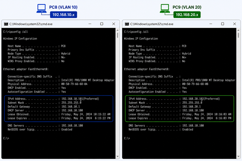
On PC8 and PC9, run ipconfig /all and confirm each machine picked up an address from the right range, with the matching default gateway.
Router-on-a-Stick vs. Layer 3 Switch
Both designs solve inter-VLAN routing, but they fit different budgets and growth plans.
| Feature | Router-on-a-Stick | Layer 3 Switch (SVI) |
|---|---|---|
| Hardware needed | One router + Layer 2 switch | One Layer 3 switch |
| Physical uplinks used | Single trunk link | No external trunk needed |
| Best for | Small labs, branch offices, CCNA practice | Growing offices, data centers |
| Routing speed | Limited by router’s single interface | Hardware-based, much faster |
| Scalability | Struggles past 4–6 VLANs on one link | Scales well with more VLANs |
For the topology in this guide, router-on-a-stick works fine because traffic volume stays low and the goal is learning the DHCP relay process, not building production-scale routing.
Common Mistakes to Avoid
- Forgetting
no shutdownon the physical interface. Sub-interfaces stay down if Fa0/0 itself is administratively down. - Mismatched encapsulation tags. The VLAN number in
encapsulation dot1Qmust match the VLAN on the switch side exactly. - Missing
ip routingon a Layer 3 switch design (not needed here, but worth remembering if you migrate away from router-on-a-stick). - Overlapping scope ranges. Never let the DHCP server’s static IP fall inside its own scope.
- Access port left in the default VLAN. Ports that aren’t explicitly assigned stay on VLAN 1 and won’t reach the intended scope.
A Note on DHCP Snooping and Security
Once the relay works, take a moment to lock it down. Rogue DHCP servers plugged into any access port can hand out bad gateway or DNS information to unsuspecting clients, and that risk grows once VLANs and relays are in play. DHCP snooping treats the uplink to the router as a “trusted” port and every access port as “untrusted,” so only trusted ports may answer with DHCP offers.
Switch(config)# ip dhcp snooping
Switch(config)# ip dhcp snooping vlan 10,20
Switch(config)# interface fastEthernet 0/1
Switch(config-if)# ip dhcp snooping trust
Switch(config-if)# exit
Leave the access ports connected to PC8 and PC9 as untrusted (the default), so any offer coming from those ports gets dropped automatically. This one setting closes off a common attack path without touching the relay configuration built earlier.
Conclusion
Centralizing DHCP on one Windows server for several VLANs comes down to three moving parts working together: the switch tagging traffic correctly, the router relaying broadcasts with the right helper address, and the DHCP server holding a matching scope for each subnet. Once these three pieces line up, adding a third or fourth VLAN later just means repeating steps 1, 4, 5, and 6 with a new VLAN number and subnet.
FAQ
Why doesn’t the client get an IP address after the trunk and VLANs are configured? Check that the sub-interface for that VLAN has both an IP address and a matching ip helper-address. A missing helper address is the most frequent cause.
Can one Windows DHCP server serve more than two VLANs? Yes. Add one more sub-interface with its own ip helper-address line, and create one more matching scope on the server. There’s no hard limit tied to this design.
Does the DHCP server need to sit on VLAN 10 specifically? No. It can sit on any VLAN, including its own dedicated management VLAN, as long as every other VLAN’s sub-interface points its ip helper-address at the server’s IP.
What port does DHCP relay use? DHCP uses UDP ports 67 (server) and 68 (client). The relay agent forwards the traffic as unicast on those same ports.
Is router-on-a-stick still relevant, or should everyone use a Layer 3 switch? Router-on-a-stick remains useful for small sites, home labs, and certification study, since it needs less hardware. Production networks with heavy inter-VLAN traffic benefit more from a Layer 3 switch.
Want more articles and tutorials like this?
Get new tutorials, security alerts, and IT tips straight to your inbox.
That’s a really useful setup for smaller networks – I’ve seen similar configurations used to manage departments effectively, especially when resources are limited.