Title: How to Configure VTP on Cisco Switches: A Complete Guide for Network Engineers
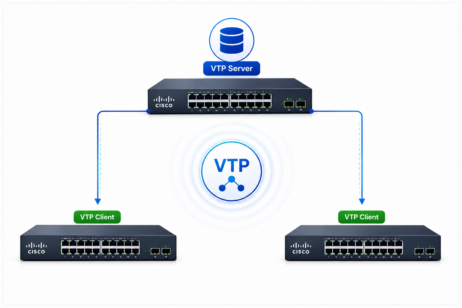
Managing VLANs across dozens of switches manually eats up hours you do not have. Every new VLAN means logging into every switch, typing the same commands, and hoping you do not mistype a VLAN ID on the seventh device. VLAN Trunking Protocol (VTP) solves this headache by letting you create VLANs once on a central switch and push those changes everywhere automatically. In this guide, I will walk you through building a real-world VTP setup using a Layer 3 backbone switch as your VTP server and access switches as clients, complete with trunk links, pruning, and troubleshooting tips I have picked up from production networks.
Table of Contents
- What Is VTP and Why Should You Care?
- Understanding the Three VTP Modes
- Network Topology and Design Considerations
- Step 1: Configure Trunk Links Between Switches
- Step 2: Set Up the VTP Server on Your Backbone Switch
- Step 3: Configure VTP Clients on Access Switches
- Step 4: Create VLANs and Assign IP Addresses
- Step 5: Enable VTP Pruning to Save Bandwidth
- Step 6: Configure Switch Management and Default Gateways
- Troubleshooting VTP: Common Problems and Fixes
- Security Best Practices for VTP Deployments
- When to Skip VTP and Use Transparent Mode Instead
- Conclusion
What Is VTP and Why Should You Care?
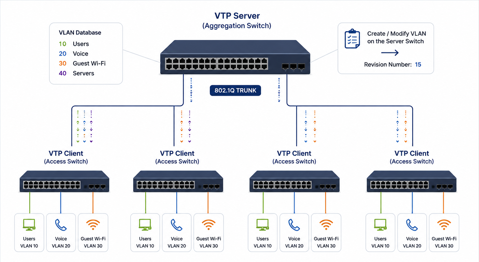
VTP stands for VLAN Trunking Protocol. Cisco developed it to help network administrators manage VLAN databases across multiple switches without touching every device individually. Think of it as a distribution system for VLAN information. You make a change on one switch, and VTP advertises that change to every other switch connected via trunk links.
Here is the practical benefit. Imagine you manage a building with five floors, each floor having its own access switch, and all switches connecting back to a central aggregation switch in the server room. Without VTP, adding a new VLAN for a guest Wi-Fi network means SSHing into six switches and typing the same vlan commands six times. With VTP, you create the VLAN once on the aggregation switch, and the protocol handles the rest.
VTP runs over trunk links only. It does not work across access ports. This matters because if you forget to configure a trunk between two switches, VTP advertisements never cross that link, and your VLANs stay out of sync.
Understanding the Three VTP Modes
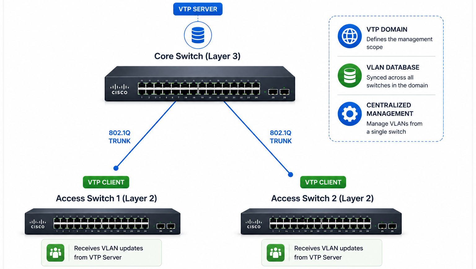
Before you start typing commands, you need to understand how each VTP mode behaves. Cisco gives you three main options, and picking the wrong one can break your network or leave you manually managing VLANs anyway.
VTP Server Mode
The VTP server holds the master VLAN database. You create, modify, and delete VLANs here. The server advertises these changes to all clients and transparent switches in the same domain. By default, Cisco switches come up in VTP server mode, which surprises many engineers who plug in a new switch and accidentally overwrite their VLAN database.
You should place the VTP server on your most stable switch, typically the Layer 3 aggregation or backbone switch. This switch usually sits at the center of your network and rarely gets replaced.
VTP Client Mode
Client switches receive VLAN information from the server and update their local databases automatically. You cannot create or delete VLANs on a client switch. If you try, the switch rejects the command. This restriction protects your VLAN database from accidental changes on edge devices.
Clients still forward VTP advertisements out their trunk ports, so a client switch can pass along updates to other clients downstream. This behavior helps VTP work across hierarchical designs where not every switch connects directly to the server.
VTP Transparent Mode
Transparent switches maintain their own VLAN database and ignore VTP advertisements from other switches. However, in VTP version 2, transparent switches still forward VTP advertisements out their trunk ports. This means they act as a bridge for VTP traffic without participating in the domain themselves.
Many experienced engineers prefer transparent mode for production networks because it eliminates the risk of a rogue switch wiping out VLANs. You lose the convenience of automatic synchronization, but you gain control and safety. I will discuss this trade-off more in a later section.
Network Topology and Design Considerations
For this guide, we will use a common two-tier design. The backbone switch sits at the aggregation layer, handling inter-VLAN routing and acting as the VTP server. Two access switches connect to the backbone via trunk links and operate as VTP clients. End devices plug into the access switches on access ports assigned to specific VLANs.
Here is how the addressing breaks down:
Table
| VLAN | Purpose | Network | Gateway |
|---|---|---|---|
| VLAN 10 | Network Infrastructure | 192.168.10.0/24 | 192.168.10.1 |
| VLAN 20 | Corporate Users | 192.168.20.0/24 | 192.168.20.1 |
| VLAN 30 | Guest Wi-Fi | 192.168.30.0/24 | 192.168.30.1 |
| VLAN 40 | VoIP Phones | 192.168.40.0/24 | 192.168.40.1 |
The backbone switch carries the default gateway for each VLAN using switched virtual interfaces (SVIs). Access switches do not route traffic. They switch frames at Layer 2 and send everything destined for another VLAN up to the backbone.
This design keeps things simple. The backbone handles all routing decisions, while access switches focus on connecting end devices. VTP fits naturally here because the backbone switch serves as the single point of VLAN management.
Step 1: Configure Trunk Links Between Switches
VTP advertisements travel exclusively over trunk links. Without trunks, VTP cannot synchronize anything. You need to configure the physical interfaces connecting your backbone switch to each access switch as 802.1Q trunks.
Start by identifying the ports. On the backbone switch, these might be GigabitEthernet 0/1 and 0/2. On Access Switch A, the uplink port might be FastEthernet 0/1. On Access Switch B, it might be FastEthernet 0/2. Your port numbers will vary depending on your hardware.
Here is the trunk configuration for the backbone switch:
Backbone-SW(config)# interface gigabitEthernet 0/1
Backbone-SW(config-if)# description *** Trunk to Access-SW-A ***
Backbone-SW(config-if)# switchport trunk encapsulation dot1q
Backbone-SW(config-if)# switchport mode trunk
Backbone-SW(config-if)# switchport trunk allowed vlan all
Backbone-SW(config-if)# no shutdown

Backbone-SW(config)# interface gigabitEthernet 0/2
Backbone-SW(config-if)# description *** Trunk to Access-SW-B ***
Backbone-SW(config-if)# switchport trunk encapsulation dot1q
Backbone-SW(config-if)# switchport mode trunk
Backbone-SW(config-if)# switchport trunk allowed vlan all
Backbone-SW(config-if)# no shutdown
The switchport trunk encapsulation dot1q command tells the switch to use 802.1Q tagging. Some older switches also support ISL, but 802.1Q has become the standard. The switchport mode trunk command forces the port into trunking mode rather than negotiating via DTP.
Now configure the access switch uplinks:
Access-SW-A(config)# interface fastEthernet 0/1
Access-SW-A(config-if)# description *** Uplink to Backbone-SW ***
Access-SW-A(config-if)# switchport trunk encapsulation dot1q
Access-SW-A(config-if)# switchport mode trunk
Access-SW-A(config-if)# no shutdown
Access-SW-B(config)# interface fastEthernet 0/1
Access-SW-B(config-if)# description *** Uplink to Backbone-SW ***
Access-SW-B(config-if)# switchport trunk encapsulation dot1q
Access-SW-B(config-if)# switchport mode trunk
Access-SW-B(config-if)# no shutdownAfter configuring both sides, verify the trunk status:
Backbone-SW# show interfaces trunk

Port        Mode         Encapsulation  Status        Native vlan
Gi0/1       on           802.1q         trunking      1
Gi0/2       on           802.1q         trunking      1

Port        Vlans allowed on trunk
Gi0/1       1-4094
Gi0/2       1-4094
If the status does not show trunking, check that both sides use the same encapsulation and that the port is not shut down. Also, remember that some switches like the Cisco 2960 use dynamic auto as the default port mode. If both sides sit in dynamic auto, the link stays as an access port. Force trunk mode on at least one side to fix this.
Step 2: Set Up the VTP Server on Your Backbone Switch
With trunks up, you can configure VTP. The backbone switch becomes your VTP server. You need to set the domain name, password, mode, and optionally enable pruning and version 2.
First, enable IP routing on the backbone switch. This step allows the switch to route traffic between VLANs later:
Backbone-SW(config)# ip routingNow configure VTP parameters:
Backbone-SW(config)# vtp mode server
Device mode already VTP Server for VLANS.

Backbone-SW(config)# vtp domain vetytop.local
Changing VTP domain name from NULL to vetytop.local

Backbone-SW(config)# vtp password cisco123
Setting device VTP password to cisco123

Backbone-SW(config)# vtp version 2
Backbone-SW(config)# vtp pruning
Let me explain each command. The vtp mode server command sets this switch as the authoritative source for VLAN information. The vtp domain command defines the management domain. Every switch participating in VTP must share the same domain name. Switches in different domains ignore each other’s advertisements.
The vtp password command adds authentication. All switches in the domain must use the same password. Without a password, any switch that connects to your network and shares the same domain name can inject VLAN information. That creates a security risk.
The vtp version 2 command enables version 2 features, including support for Token Ring VLANs and consistency checks. Most modern networks run version 2 or version 3. If you have older switches that only support version 1, leave this at the default.
The vtp pruning command enables VTP pruning for the entire domain. I will explain pruning in detail later, but for now, know that it prevents unnecessary broadcast traffic from crossing trunk links to switches that do not have ports in those VLANs.
Verify your VTP server configuration:
Backbone-SW# show vtp status

VTP Version capable             : 1 to 3
VTP version running             : 2
VTP Operating Mode              : Server
VTP Domain Name                 : vetytop.local
VTP Pruning Mode                : Enabled
VTP V2 Mode                     : Enabled
VTP Traps Generation            : Disabled
Device ID                       : aabb.cc00.0100
Configuration last modified by 0.0.0.0 at 0-0-00 00:00:00
Local updater ID is 0.0.0.0 (no valid interface found)

Feature VLAN:
--------------
VTP Operating Mode                : Server
Maximum VLANs supported locally   : 1005
Number of existing VLANs          : 5
Configuration Revision            : 0
Pay attention to the Configuration Revision number. Right now it shows 0 because you have not created any VLANs yet. Every time you add or remove a VLAN, this number increments. Client switches use this number to decide whether to update their database.
Step 3: Configure VTP Clients on Access Switches
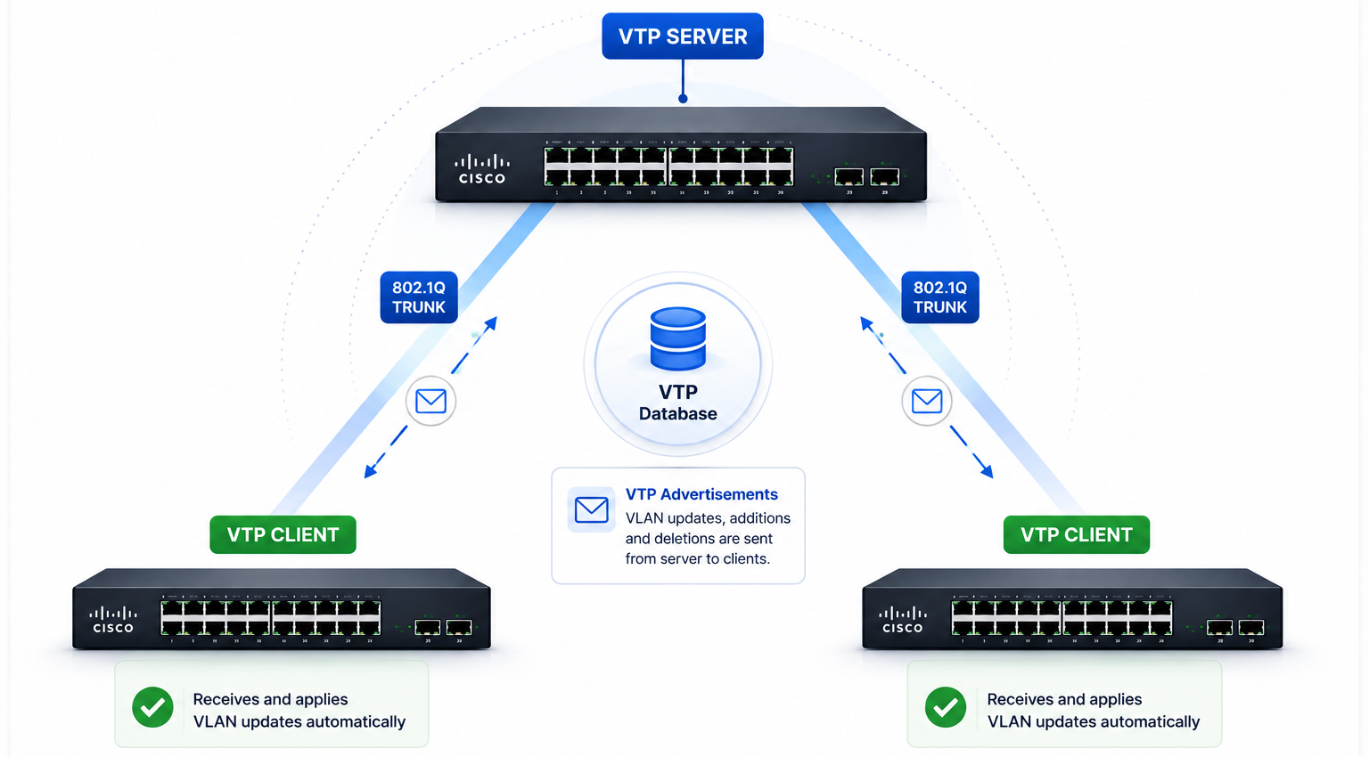
Next, configure your access switches to receive VLAN information from the backbone. The process mirrors the server setup but uses vtp mode client instead.
On Access Switch A:
Access-SW-A(config)# vtp mode client
Setting device to VTP Client mode for VLANS.

Access-SW-A(config)# vtp domain vetytop.local
Changing VTP domain name from NULL to vetytop.local

Access-SW-A(config)# vtp password cisco123
Setting device VTP password to cisco123

Access-SW-A(config)# vtp version 2
On Access Switch B:
Access-SW-B(config)# vtp mode client
Setting device to VTP Client mode for VLANS.

Access-SW-B(config)# vtp domain vetytop.local
Changing VTP domain name from NULL to vetytop.local

Access-SW-B(config)# vtp password cisco123
Setting device VTP password to cisco123

Access-SW-B(config)# vtp version 2
After entering these commands, verify that the clients have joined the domain:
Access-SW-A# show vtp status

VTP Version capable             : 1 to 3
VTP version running             : 2
VTP Operating Mode              : Client
VTP Domain Name                 : vetytop.local
VTP Pruning Mode                : Enabled
VTP V2 Mode                     : Enabled
Configuration Revision          : 0
Notice that the client shows Configuration Revision: 0 and the pruning mode shows Enabled even though you did not type vtp pruning on the client. The pruning state propagates from the server automatically. When the server creates VLANs and the revision number increases, the client will sync and display the updated number.
If the domain name does not match exactly, VTP will not synchronize. The domain name is case-sensitive. vetytop.local and Vetytop.local count as different domains.
Step 4: Create VLANs and Assign IP Addresses
Now for the part that saves you time. You create all VLANs on the backbone switch, and VTP pushes them to the access switches automatically.
Create the VLANs on the backbone:
Backbone-SW(config)# vlan 10
Backbone-SW(config-vlan)# name Network-Devices

Backbone-SW(config)# vlan 20
Backbone-SW(config-vlan)# name Corporate-Users

Backbone-SW(config)# vlan 30
Backbone-SW(config-vlan)# name Guest-WiFi

Backbone-SW(config)# vlan 40
Backbone-SW(config-vlan)# name VoIP-Phones
After creating these VLANs, check the revision number:
Backbone-SW# show vtp status | include Revision
Configuration Revision            : 4
The revision number jumped to 4 because you created four VLANs. Now check the client switches:
Access-SW-A# show vlan brief

VLAN Name                             Status    Ports
---- -------------------------------- --------- -------------------------------
1    default                          active    Fa0/2, Fa0/3, Fa0/4, Fa0/5
                                                Fa0/6, Fa0/7, Fa0/8, Fa0/9
                                                Fa0/10, Fa0/11, Fa0/12
10   Network-Devices                  active
20   Corporate-Users                  active
30   Guest-WiFi                       active
40   VoIP-Phones                      active
1002 fddi-default                     act/unsup
1003 token-ring-default               act/unsup
1004 fddinet-default                  act/unsup
1005 trnet-default                    act/unsup
The access switch now knows about VLANs 10, 20, 30, and 40 without you typing a single vlan command on that device. VTP did the work.
Next, configure the Layer 3 interfaces on the backbone switch so devices in each VLAN can route to each other and reach external networks:
Backbone-SW(config)# interface vlan 10
Backbone-SW(config-if)# description *** Gateway for Network Devices ***
Backbone-SW(config-if)# ip address 192.168.10.1 255.255.255.0
Backbone-SW(config-if)# ip helper-address 192.168.10.100
Backbone-SW(config-if)# no shutdown

Backbone-SW(config)# interface vlan 20
Backbone-SW(config-if)# description *** Gateway for Corporate Users ***
Backbone-SW(config-if)# ip address 192.168.20.1 255.255.255.0
Backbone-SW(config-if)# ip helper-address 192.168.10.100
Backbone-SW(config-if)# no shutdown

Backbone-SW(config)# interface vlan 30
Backbone-SW(config-if)# description *** Gateway for Guest WiFi ***
Backbone-SW(config-if)# ip address 192.168.30.1 255.255.255.0
Backbone-SW(config-if)# ip helper-address 192.168.10.100
Backbone-SW(config-if)# no shutdown

Backbone-SW(config)# interface vlan 40
Backbone-SW(config-if)# description *** Gateway for VoIP Phones ***
Backbone-SW(config-if)# ip address 192.168.40.1 255.255.255.0
Backbone-SW(config-if)# ip helper-address 192.168.10.100
Backbone-SW(config-if)# no shutdown
The ip helper-address command forwards DHCP broadcasts to your DHCP server at 192.168.10.100. Without this command, devices in these VLANs cannot obtain IP addresses automatically because routers do not forward broadcast traffic by default.
Verify your SVIs are up:
Backbone-SW# show ip interface brief | include Vlan
Vlan10                  192.168.10.1    YES manual up                    up
Vlan20                  192.168.20.1    YES manual up                    up
Vlan30                  192.168.30.1    YES manual up                    up
Vlan40                  192.168.40.1    YES manual up                    up
If an SVI shows down/down, you have not assigned any access ports to that VLAN yet, or the VLAN does not exist in the database. Create the VLAN first, then assign a port.
Step 5: Enable VTP Pruning to Save Bandwidth
VTP pruning prevents broadcast, multicast, and unknown unicast traffic from crossing trunk links to switches that do not have active ports in those VLANs. Without pruning, if a device in VLAN 20 sends a broadcast, that broadcast floods across every trunk link in your network, even to switches where no one uses VLAN 20.
You already enabled pruning on the server with the vtp pruning command. The setting propagates to all clients. But you can also control pruning manually on individual trunk links if you want finer control.
To see which VLANs are eligible for pruning on a trunk:
Backbone-SW# show interfaces gigabitEthernet 0/1 switchport

Trunking VLANs Enabled: All
Pruning VLANs Enabled: 2-1001
Capture Mode Disabled
Capture VLANs Allowed: ALL
By default, VLANs 2 through 1001 are pruning-eligible. VLAN 1 and the reserved VLANs 1002-1005 never get pruned.
If you want to manually exclude certain VLANs from pruning on a specific trunk, use this command:
Backbone-SW(config)# interface gigabitEthernet 0/1
Backbone-SW(config-if)# switchport trunk pruning vlan remove 30
Now VLAN 30 traffic will always cross this trunk, even if the downstream switch has no ports in VLAN 30. This setting makes sense if you have a wireless access controller or a server that roams between switches and needs VLAN 30 everywhere.
Step 6: Configure Switch Management and Default Gateways
Your access switches need IP addresses too, but not for routing user traffic. They need management IP addresses so you can SSH into them remotely. Place the management IP on the VLAN that makes sense for your organization, typically VLAN 10 for infrastructure devices.
On Access Switch A:
Access-SW-A(config)# interface vlan 10
Access-SW-A(config-if)# ip address 192.168.10.2 255.255.255.0
Access-SW-A(config-if)# no shutdown

Access-SW-A(config)# ip default-gateway 192.168.10.1
On Access Switch B:
Access-SW-B(config)# interface vlan 10
Access-SW-B(config-if)# ip address 192.168.10.3 255.255.255.0
Access-SW-B(config-if)# no shutdown

Access-SW-B(config)# ip default-gateway 192.168.10.1
The ip default-gateway command points to the backbone switch’s VLAN 10 SVI. Without this command, the access switch cannot reach subnets outside its own management VLAN. Remember that access switches operate at Layer 2. They do not build routing tables. The default gateway tells them where to send packets destined for remote networks.
Test connectivity from the access switch:
Access-SW-A# ping 192.168.10.1
Type escape sequence to abort.
Sending 5, 100-byte ICMP Echos to 192.168.10.1, timeout is 2 seconds:
!!!!!
Success rate is 100 percent (5/5), round-trip min/avg/max = 1/1/4 ms
If the ping fails, check that the trunk link is up, that VLAN 10 exists on both switches, and that the SVI on the backbone is not shut down.
Troubleshooting VTP: Common Problems and Fixes
Even with a solid configuration, VTP can trip you up. Here are the issues I see most often in production and how to fix them.
Clients Not Syncing VLANs
If your access switch shows only the default VLANs, start with the basics. Verify the trunk link is active:
Access-SW-A# show interfaces trunkIf no trunks appear, reconfigure the port as shown in Step 1. Next, confirm the domain name and password match exactly:
Access-SW-A# show vtp status
Backbone-SW# show vtp status
Compare the VTP Domain Name and MD5 digest fields. If the domain names differ, the client will not sync. If the passwords differ, the MD5 digest will not match, and the client will ignore advertisements.
The Revision Number Trap
This problem destroys networks. Imagine you have a lab switch that was previously a VTP server with revision number 15. You erase the configuration and ship it to a remote office. When someone plugs it into the production network, the switch still holds revision number 15. If your production server sits at revision number 12, every switch in the domain overwrites its VLAN database with the lab switch’s old configuration. All your carefully planned VLANs vanish.
Before connecting any used switch to your network, reset the revision number to zero. The easiest way is to change the switch to transparent mode and back:
Switch(config)# vtp mode transparent
Switch(config)# vtp mode client
Transparent mode resets the revision number to 0. When you switch back to client mode, the switch accepts the server’s database because the server now has the higher revision number.
Forcing a VTP Update
VTP does not have a manual push button. Updates only trigger when the revision number changes. If you need to force clients to sync immediately, create a dummy VLAN and delete it on the server:
Backbone-SW(config)# vlan 999
Backbone-SW(config-vlan)# exit
Backbone-SW(config)# no vlan 999
This action increments the revision number and triggers an advertisement. All clients will sync within seconds.
VTP Pruning Blocking Needed Traffic
If devices in a VLAN cannot communicate across switches, pruning might be removing that VLAN from the trunk. Check which VLANs are pruned:
Backbone-SW# show interfaces trunk

Port        Vlans in spanning tree forwarding state and not pruned
Gi0/1       1,10,20,30,40
Gi0/2       1,10,20,40
If VLAN 30 is missing from Gi0/2, pruning removed it because Access-SW-B has no active ports in VLAN 30. Either assign a port to VLAN 30 on that switch or manually add VLAN 30 to the trunk’s pruning-eligible list.
Security Best Practices for VTP Deployments
VTP can simplify your life, but it also opens a door for accidents and attacks. Follow these practices to keep your network safe.
Always set a VTP password. Without one, any switch that connects to your trunk and guesses your domain name can inject VLAN data. Use a strong password and document it in your network management system.
Never use the default VTP domain name. A switch out of the box has a NULL domain name, but it will adopt the first domain name it hears. If you leave your network with the default name, a rogue switch can join easily.
Check revision numbers before adding switches. Make this a mandatory step in your deployment checklist. A single switch with a high revision number can wipe out every VLAN in your building.
Consider using VTP version 3 if your hardware supports it. Version 3 introduces the vtp mode off command, which completely disables VTP and stops forwarding advertisements. It also supports hidden and secret password options that do not display the password in plain text in the configuration file.
When to Skip VTP and Use Transparent Mode Instead
Despite the convenience, many senior network engineers avoid VTP entirely. They configure every switch in transparent mode and manage VLANs manually or through automation tools like Ansible or Python scripts.
The argument against VTP is simple. The time saved creating VLANs does not outweigh the risk of a single mistake taking down your network. Also, you still need to log into every access switch to assign ports to VLANs. VTP only syncs the VLAN database, not port assignments.
Transparent mode gives you complete control. Each switch maintains its own VLAN database independently. You eliminate the revision number risk entirely. If you have fewer than twenty switches, transparent mode might actually save you time because you do not need to worry about VTP troubleshooting.
For large campus networks with hundreds of switches, VTP makes more sense. The key is discipline. Document your domain, control who can make changes, and always verify revision numbers before connecting new hardware.
Conclusion
VTP remains a useful tool for managing VLANs at scale, but it demands respect. In this guide, you learned how to build a complete VTP deployment from the ground up. You configured trunk links between a Layer 3 backbone switch and access switches, set up the VTP server and clients with matching domain names and passwords, created VLANs that synchronized automatically, enabled pruning to conserve bandwidth, and assigned management IPs for remote access.
You also learned how to troubleshoot the most common VTP headaches, including domain mismatches, revision number surprises, and pruning-related connectivity issues. Remember that VTP works only over trunk links, so always verify your trunk status before chasing VTP problems.
If you manage a small network, transparent mode might serve you better. If you manage a multi-building campus, VTP saves serious time when you configure it with discipline. Whichever path you choose, document your VLAN design, control your revision numbers, and never plug in a used switch without resetting its VTP database first.
Want more articles and tutorials like this?
Get new tutorials, security alerts, and IT tips straight to your inbox.